
 Flight Pro Sim - The Instrument Panel...
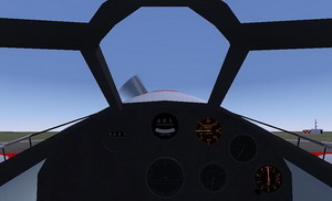
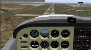 The aircraft within this simulator can have both a 2-dimensional instrument panel and a 3-dimensional cockpit. The 3-dimensional cockpit provide a much more realistic pilot-eye view.
The default Cessna 172P (c172p) has both a 3-dimensional and 2-dimensional cockpit. The 3-dimensional cockpit is activated by default when you start, but you can over-lay the 2-dimensional instrument panel by selecting from the menu
View -> Toggle 2D Panel, or pressing the “P” key.
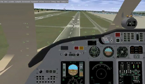
While a complete description of all the functions of the instrument panel of a Cessna is beyond the scope of this guide, we will at least try to outline the main flight instruments or gauges.
All panel levers and knobs can be operated with the mouse To change a control, just click with the left/middle mouse button on the corresponding knob/lever.
Let us start with the most important instruments any simulator pilot must know. In the center of the instrument panel, in the upper row, you will find the artificial horizon (attitude indicator) displaying pitch and bank of your plane. It has pitch marks as well as bank marks at 10, 20, 30, 60, and 90 degrees.
Left to the artificial horizon, you’ll see the airspeed indicator. Not only does it provide a speed indication in knots but also several arcs showing characteristic velocity rages you have to consider. At first, there is a green arc indicating the normal operating range of speed with the flaps fully retracted. The white arc indicates the range of speed with flaps in action. The yellow arc shows a range, which should only be used in smooth air. The upper end of it has a red radial indicating the speed you must never exceeded - at least as long as you won’t brake your plane.
Below the airspeed indicator you can find the turn indicator. The airplane in the middle indicates the roll of your plane. If the left or right wing of the plane is aligned with one of the marks, this would indicate a standard turn, i.e. turn of 360 degrees in exactly two minutes.
Below the plane, still in the turn indicator, is the inclinometer. It indicates if rudder and ailerons are coordinated. During turns, you always have to operate aileron and rudder in such a way that the ball in the tube remains centered; otherwise the plane is skidding. A simple rule says: “Step onto the ball”, i.e. step onto the left rudder pedal in case the ball is on the l.h.s.
If you don’t have pedals or lack the experience to handle the proper ratio between aileron/rudder automatically, you can start with the option --enable-auto-coordination.
To the r.h.s of the artificial horizon you will find the altimeter showing the height above sea level (not ground!) in hundreds of feet. Below the altimeter is the vertical speed indicator indicating the rate of climbing or sinking of your plane in hundreds of feet per minute. While you may find it more convenient to use then the altimeter in cases, keep in mind that its display usually has a certain lag in time.
 Further below the vertical speed indicator is the RPM (rotations per minute) indicator, which displays the rotations per minute in 100 RPMs. The green arc marks the optimum region for long-time flight.
The group of the main instruments further includes the gyro compass being situated below the artificial horizon. Besides this one, there is a magnetic compass sitting on top of the panel.
Four of these gauges being arranged in the from of a “T” are of special importance: The air speed indicator, the artificial horizon, the altimeter, and the compass should be scanned regularly during flight.
Besides these, there are several supplementary instruments. To the very left you will find the clock, obviously being an important tool for instance for determining turn rates. Below the clock there are several smaller gauges displaying the technical state of your engine. Certainly the most important of them is the fuel indicator - as any pilot should know.
The ignition switch is situated in the lower left corner of the panel. It has five positions: “OFF”, “L”, “R”, “BOTH”, and “START”. The first one is obvious. “L” and “R” do not refer to two engines (actually the Cessna does only have one) but to two magnetos being present for safety purposes. The two switch positions can be used for test purposes during preflight. During normal flight the switch should point on “BOTH”. The extreme right position is for using a battery-powered starter (to be operated with the “s” key).
Like in most flight simulators, you actually get a bit more than in a real plane. The red field directly below the gyro compass displays the state of the brakes, i.e., it is lit in case of the brakes being engaged. The instruments below indicate the position of your yoke. This serves as kind of a compensation for the missing forces you feel while pushing a real yoke. Three of the arrows correspond to the three axes of your yoke/pedal controlling nose up/down, bank left/right, rudder left/right, and throttle. (Keep in mind: They do not reflect the actual position of the plane!) The left vertical arrow indicates elevator trim.
The right hand side of the panel is occupied by the radio stack. Here you find two VOR receivers (NAV), an NDB receiver (ADF) and two communication radios (COMM1/2) as well as the autopilot.
The communication radio is used for communication with air traffic facilities; it is just a usual radio transceiver working in a special frequency range. The frequency is displayed in the “COMM” field. Usually there are two COM transceivers; this way you can dial in the frequency of the next controller to contact while still being in contact with the previous one.
The COM radio can be used to display ATIS messages as well. For this purpose, just to dial in the ATIS frequency of the relevant airport.
The VOR (Very High Frequency Omni-Directional Range) receiver is used for course guidance during flight. The frequency of the sender is displayed in the ”NAV” field. In a sense, a VOR acts similarly to a light house permitting to display the position of the aircraft on a radial around the sender. It transmits one omni-directional ray of radio waves plus a second ray, the phase of which differs from the first one depending on its direction (which may be envisaged as kind of a “rotating” signal). The phase difference between the two signals allows evaluating the angle of the aircraft on a 360 degrees circle around the VOR sender, the so-called radial. This radial is then displayed on the gauges NAV1 and NAV2, resp., left to frequency field. This way it should be clear that the VOR display, while indicating the position of the aircraft relative to the VOR sender, does not say anything about the orientation of the plane.
Below the two COM/NAV devices is an NDB receiver called ADF (automatic direction finder). Again there is a field displaying the frequency of the facility. The ADF can be used for navigation, too, but contrary to the VOR does not show the position of the plane in a radial relative to the sender but the direct heading from the aircraft to the sender. This is displayed on the gauge below the two NAV gauges.
Above the COMM1 display you will see three LED's in the colors blue, amber, and white indicating the outer, middle, and, inner, resparker beacon. These show the distance to the runway threshold during landing. They do not require the input of a frequency.
Below the radios you will find the autopilot. It has five keys for WL = “Wing-Leveler”, “HDG” = “Heading”, NAV, APR = “Glide-Slope”, and ALT = “Altitude”. These keys when engaged hold the corresponding property.
You can change the numbers for the radios using the mouse. For this purpose, click left/right to the circular knob below the corresponding number. The corresponding switch left to this knob can be used for toggling between the active/standby frequency.
It should be noted, that you can neglect these radio instruments as long as you are strictly flying according to VFR (visual flight rules). For those wanting to do IFR (instrument flight rules) flights, it should be mentioned that this simulator includes a huge database of navaids worldwide.
Finally, you find the throttle, mixture, and flap control in the lower right of the panel (recall, flaps can be set via [ and ] or just using the mouse).
As with the keyboard, the panel can be re-configured using configuration files. As these have to be plane specific, they can be found under the directory of the corresponding plane.
With so much of the world to see, so many aircraft to fly, and so many excited new players joining in, you’ll be hooked on FlightProSim for a long time. We’re excited to be able to offer you one of the most all-inclusive flight simulator experiences ever known. So hop in, buckle up, and fire your engines.
The ride is just beginning!

Charlie
Taylor and The FlightProSim Team!!
Make your travel dreams a reality and take to the skies!
We’ll see you when you touch down.
Order Your No Risk Copy Today
Yes you get it ALL...
... No holding back, purchase now and you really do get it all. Here is a quick list of what you will receive in case you missed the above details:
Order now to receive:
![]() The
full FlightProSim™ Game - Be soaring through the sky in 5 minutes
time
The
full FlightProSim™ Game - Be soaring through the sky in 5 minutes
time
![]() 100+
planes / helicopters - This will keep you entertained for months
100+
planes / helicopters - This will keep you entertained for months
![]() Full
members area access for life- Download it all
again next month if you want to
Full
members area access for life- Download it all
again next month if you want to
![]() Comprehensive
flight manual and tutorials - Learn how to fly fast
Comprehensive
flight manual and tutorials - Learn how to fly fast
![]() Ongoing
support - from our dedicated Help Desk Staff
Ongoing
support - from our dedicated Help Desk Staff
![]() 100%
Free Updates / Upgrades - Always have the latest version
100%
Free Updates / Upgrades - Always have the latest version
![]() Multi
PC License - Use FlightProSim on as many computers as you want
Multi
PC License - Use FlightProSim on as many computers as you want
So what are you waiting for, try out FlightProSim risk free for 14 days.
» Game CD
» Africa
» North America
» South America
» Eurasia
» Oceania
» Support
. Part of the IDB Group. © 2002 - 2010. All rights Reserved. Terms of Use | Privacy Policy